
GSM 4 Click


Το GSM 4 click είναι μια λύση συμπαγούς τετραπλής ζώνης GSM κυψελοειδούς δικτύου, που διαθέτει το τετραπλό συγκρότημα 2.5G GSM / GPRS SARA-G350. Αυτή η ενότητα διαθέτει ένα πλήρες σύνολο επιλογών για την κυτταρική δικτύωση και την επικοινωνία, όπως η ένδειξη κατάστασης δικτύου, ανίχνευση μπλοκαρίσματος, ενσωματωμένα πρωτόκολλα Διαδικτύου, όπως TCP / IP, UDP, FTP, PPP, HTTP, SMTP. , κι αλλα. Η ταχύτητα επικοινωνίας δεδομένων έχει βαθμολογηθεί έως 42,8 για την ανερχόμενη ζεύξη και 85,6 kbps για σύνδεση προς τα κάτω. Αυτή η ενότητα προσφέρει ενσωματωμένη ηχητική διασύνδεση υψηλής ποιότητας, επιτρέποντας τη φωνητική επικοινωνία μέσω του ενσωματωμένου συνδέσμου ακουστικών 3,5 χιλ. Και της υποδοχής USB.
GSM 4 click is a compact quad-band GSM cellular network communication solution, featuring the quad-band 2.5G GSM/GPRS SARA-G350 module. This module features a full set of options for the cellular networking and communication, such as the network status indication, jamming detection, embedded internet protocols, including TCP/IP, UDP, FTP, PPP, HTTP, SMTP, full GPRS multislot class 10 implementation, and more. Data communication speed is rated up to 42.8 for the uplink and 85.6 kbps for downlink connection. This module offers high quality integrated audio interface, allowing voice communication over the onboard 3.5mm headset connector, and the USB connector.
GSM 4 click supports quad-band GSM/GPRS, allowing it to be used worldwide. A wide range of communication protocols and connectivity options, packed in the compact size module, driven by the simple AT command interface via the UART bus, make this click board™ a complete solution for a wide range of M2M applications, such as mobile Internet terminals, automatic meter reading (AMR), remote monitoring automation and control (RMAC), surveillance and security, road pricing, asset tracking, wireless points of service (POS) and similar applications, which rely on a cellular network connection.
HOW DOES IT WORK?
GSM 4 click is equipped with the SARA-G350, a compact, quad-band 2.5G GSM/GPRS module, from u-blox. It covers frequencies of 850/900 MHz and frequencies of 1800/1900 MHz. It is class 10 compliant, featuring 4 download slots / 2 upload slots, supporting 5 slots in total. This module is the main component of the click board and it consists of a number of internal blocks or sections, such as antenna switching section, RF transceiver section, memory, power management, and most importantly - the cellular baseband processor. The module interface consists of several lines used to report the device and the network status, SIM card interface lines, UART interface lines, and device control lines. These lines are routed to the respective elements of the click board.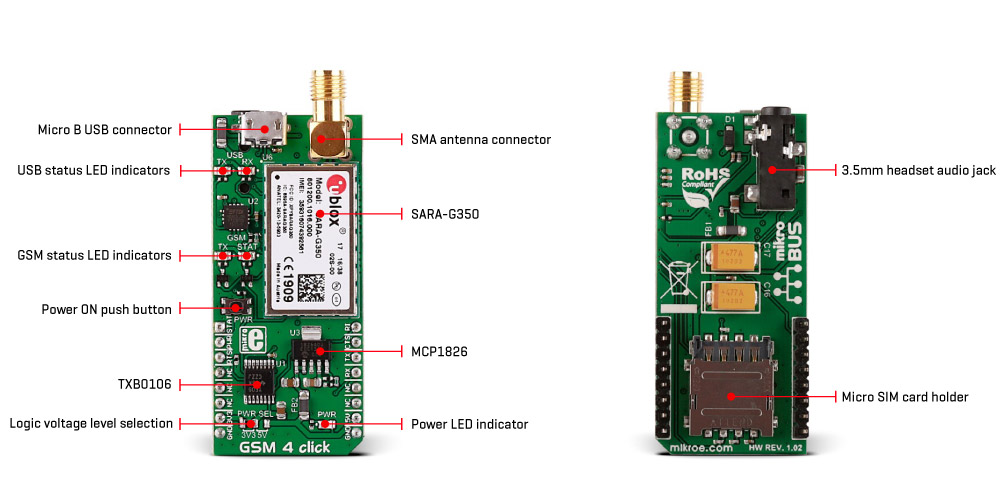
The SARA-G350 module has to be powered by a clean and stable power supply. The voltage needed for the module to work properly is about 4V and it is derived from the 5V mikroBUS™ rail, through the MCP1826, a 1A low drop output (LDO) regulator from Microchip. Although the SARA-G350 is a low power device, the cellular network modules in general, are notorious for their high power consumption, so the 1A LDO had to be used.
Digital sections of the SARA-G350 are internally supplied by 1.8V, so it is necessary to condition the communication bus lines which connect the host MCU with the module. SARA-G350 outputs 1.8V output from its internal LDO, providing a needed reference voltage for one side of the TXB0106, a 6bit bidirectional level shifting and voltage translator with automatic direction sensing, from Texas Instruments. The reference voltage for the other side of the level shifter is taken from the onboard SMD jumper, labeled as I/O Level This jumper is used to select between 3.3V and 5V from the mikroBUS™, depending on the used MCU type and its logic voltage level requirements.
UART interface supports baud rates from 2400 bps to 115.2 kbps and automatic baud rate detection for up to 115.2 kbps. The automatic baud rate detection mode is set by default. The UART bus of the SARA-G350 module is connected to one side of the level shifter, while the other side (shifted) is connected to the respective mikroBUS™ UART pins (TX and RX). However, the SARA-G350 module is designed as the traditional DCE device (Data Communication Equipment) offering the full UART pin count, including the hardware flow control pins (CTS, RTS). These pins are routed to the mikroBUS™ CS (RTS) and the INT pin (CTS) and are used if the hardware flow control is enabled. The RI pin is the Ring Indicator, and it is routed to the mikroBUS™ PWM pin.
GSM 4 click offers USB interface via the micro USB connector, routed to the dedicated USB to UART IC. The FT230X IC is used for this purpose, a well-established USB to UART solution from FTDI Company, used on many MikroElektronika products. Besides to the level shifter IC, the same UART lines from the SARA-G350 are also routed to this USB to UART IC, offering an easy access to the SARA-G350 module via the personal computer and USB connection.
The board is populated with two pairs of LED indicators, which are used to provide a visual feedback of the Click board™ communication status. One pair of LEDs belongs to the USB section and the USB to UART IC, while the second pair of LED indicators belongs to the SARA-G350 module itself. In addition, one pair of LEDs is labeled with USB, while the second pair of LEDs is labeled with GSM. This makes it easy to understand which LEDs are used for the specific function.
GSM LEDs: These LEDs are routed to the GPIO1 and GPIO2 pins of the SARA-G350 module. GPIO 1 pin is routed to a red LED labeled as TX, while the GPIO pin 2 is routed to a yellow LED, labeled as STAT. In addition, the GPIO 2 pin is also routed to the mikroBUS™, allowing the host MCU to read its state. By default, the GPIO 1 pin is configured as the general GPIO pin with the internal pull-down resistor activated, and the GPIO 2 pin is configured to enable or disable the supply of u-blox positioning chips and modules. However, these pins can be configured for a wide range of functions by the user, via simple AT commands. For the complete list of configurable options, please consult the included datasheet.
USB LEDs: Two LEDs, red and yellow, labeled as TX and RX are used to provide a visual feedback of the USB to UART communication: yellow RX LED will indicate data which is being received via the USB, while the red TX LED will indicate the data transmitted from the module, via the USB. These two LEDs provide a visual feedback of the USB to UART communication.
The PWR_ON (PWRKEY) pin is routed to the mikroBUS™ RST pin, and it is used to manually power up the Click board™. Asserting this pin to a LOW logic level for at least 5 ms will activate the SARA-G350 module. This pin is also routed to the onboard push-button labeled as PWR, which can be used to set the state of this pin to a LOW logic level, resulting with the activation of the module. To properly detach from the network and store the working parameters in its non-volatile memory, the module should be safely powered off, by issuing the AT+CPWROFF command. Abrupt termination of the power supply might lead to a loss of the current parameter settings and improper detach from the network.
The SARA-G350 module offers extensive audio features, including Half rate, full rate, enhanced full rate and adaptive multi-rate voice codecs, superior echo cancellation and noise reduction, multiple pre-programmed audio profiles, specialized hands-free algorithm, all configurable with the AT commands. The audio DSP section is integrated inside the module and it requires only a few external components. The headset can be connected via the 4-pole 3.5mm audio jack.
The Micro SIM card holder on the back of the click board™ is used to install a micro SIM card. This device cannot be used without the valid SIM card, which allows connection to the cellular network. Both 1.8V and 3V SIM card types are supported.
SPECIFICATIONS
| Type | GSM |
| Applications | Remote monitoring automation, asset tracking, surveillance and security, home automation systems, point of sales terminals etc. |
| On-board modules | u-blox SARA-G3 series 2.5G GSM/GPRS cellular quad-band modul |
| Key Features | GSM Quad-band 850/1900, 900/1800 MHz, Maximum output power -8dBm, IPv4/IPv6 dual-stack |
| Key Benefits | Power consumption in idle-mode 0.3mA |
| Interface | GPIO,UART,USB |
| Input Voltage | 3.3V or 5V |
| Compatibility | mikroBUS |
| Click board size | L (57.15 x 25.4 mm) |
PINOUT DIAGRAM
This table shows how the pinout on GSM 4 click corresponds to the pinout on the mikroBUS™ socket (the latter shown in the two middle columns).
| Notes | Pin | Pin | Notes | ||||
|---|---|---|---|---|---|---|---|
| Power ON status | STAT | 1 | AN | PWM | 16 | RI | Ring indication |
| Hardware reset of the module | RST | 2 | RST | INT | 15 | CTS | Clear to send |
| Ready To Send | RTS | 3 | CS | RX | 14 | TXD | Transmit data |
| NC | 4 | SCK | TX | 13 | RXD | Receive data | |
| NC | 5 | MISO | SCL | 12 | NC | ||
| NC | 6 | MOSI | SDA | 11 | NC | ||
| Power Supply | +3V3 | 7 | 3.3V | 5V | 10 | +5V | Power Supply |
| Ground | GND | 8 | GND | GND | 9 | GND | Ground |
ONBOARD SETTINGS AND INDICATORS
| Label | Name | Default | Description |
|---|---|---|---|
| JP1 | I/O Level | Left | Logic level voltage selection: left position 3V3, right position 5V |
| PWR | PWR | - | PWR indication LED |
| TX | TX | - | TX LED indicator – configurable (GPIO pin 1) |
| STAT | STAT | - | STAT LED indicator – configurable (GPIO pin 2) |
| TX | TX | - | USB to UART transmission (TX) LED indicator |
| RX | RX | - | USB to UART reception (RX) LED indicator |
SOFTWARE SUPPORT
We provide a library for GSM 4 click on our Libstock page, as well as a demo application (example), developed using MikroElektronika compilers and mikroSDK. The provided click library is mikroSDK standard compliant. The demo application can run on all the main MikroElektronika development boards.
Library Description
The library carries a generic command parser adopted for AT command based modules. Generic parser.
Key functions:
gsm4_cmdSingle- Sends a provided command to the module.gsm4_setHandler- Handler assignation to the provided command.gsm4_modulePower- Turns on the module.
Examples Description
The example demo application waits for the call, and after the call is received the parser will get hang up.
This code snippet shows how a generic parser should be properly initialized. Before the initialization, the module must be turned on, and in addition to this the hardware flow control should also be turner on.
Commands:
- The first command negotiates the baud rate with the module.
- The second command turns the echo off.
- The third command enables hardware flow control - necessary in case of UART polling.
- The fourth command sets up default message foramt.
// MODULE POWER ON gsm4_hfcEnable( true ); gsm4_modulePower( true );
// MODULE INIT gsm4_cmdSingle( "AT" ); gsm4_cmdSingle( "ATE0" ); gsm4_cmdSingle( "AT+IFC=2,2" ); gsm4_cmdSingle( "AT+CMGF=1" );
Along with the demo application, timer initialization functions are provided. Note that the timer is configured according to the default development system and MCUs, changing the system or MCU may require an update of timer init and timer ISR functions.
The full application code, and ready to use projects can be found on our Libstock page.
Other mikroE Libraries used in the example:
- String
- Conversion
Additional notes and information
Depending on the development board you are using, you may need USB UART click, USB UART 2 click or RS232 click to connect to your PC, for development systems with no UART to USB interface available on the board. The terminal available in all MikroElektronika compilers, or any other terminal application of your choice, can be used to read the message.
MIKROSDK
This Click board™ is supported with mikroSDK - MikroElektronika Software Development Kit. To ensure proper operation of mikroSDK compliant Click board™ demo applications, mikroSDK should be downloaded from the LibStock and installed for the compiler you are using.
For more information about mikroSDK, visit the official page.
DOWNLOADS
mikroBUS™ Standard specification
LibStock: GSM 4 click Examples
Learn Article - Introducing The GSM
LibStock: mikroSDK
GSM 4 click schematic
GSM 4 click: 2D and 3D files
SARA-G3 datasheet
Click Boards™ Catalog


